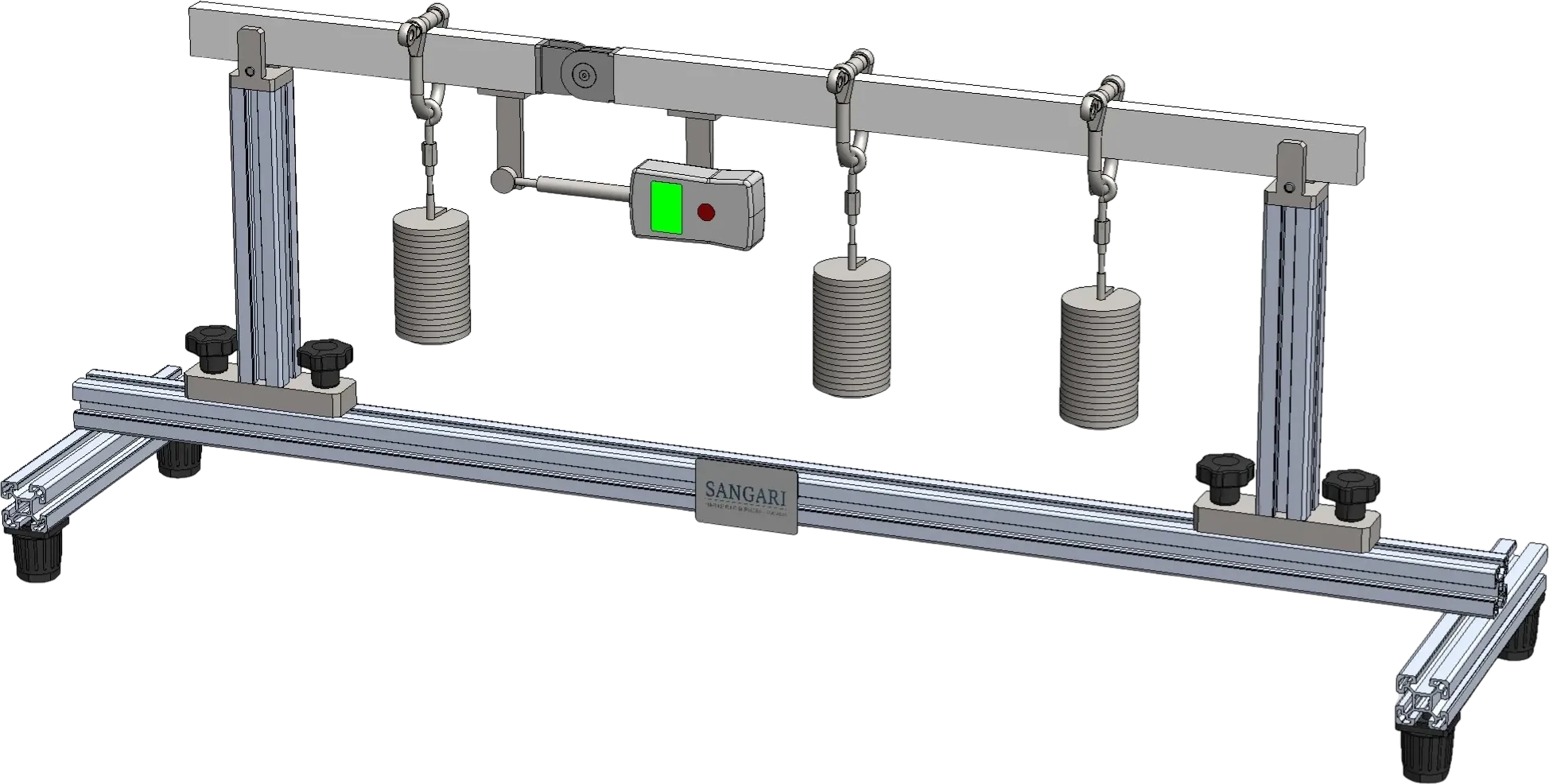
Experimental apparatus for the direct measurement of shear force and bending moment in a simply-supported beam
A simply-supported beam cut at one-third of its span and rejoined by a low-friction two-degree-of-freedom hinge. Two calibrated force gauges across the hinge read the internal shear force and bending moment at that section directly — turning the method of sections from a sketch on the blackboard into a measurement the students can verify against their own equilibrium calculations.
Experiments
Calculation of the support reactions from the static conditions of equilibrium
Application of the method of sections to determine internal forces and moments:
under a single point load
under two or three point loads
Construction of the shear-force diagram
Construction of the bending-moment diagram
Comparison of calculated and measured values for shear force and bending moment
Beam & supports
Total length1100 mm
Span between supports800 mm
Hinge position1/3 of the span, 2 DoF, low-friction
Supports2 roller supports with horizontal-alignment adjusters
Load positioning1000 mm tape, 1 mm graduation
Loading1 to 3 simultaneous point loads, any position along the beam
Measurement
Shear force (Q)force gauge, ±50 N
Bending moment (M)force gauge (±100 N) × lever arm 100 mm → ±10 Nm
Zero adjustmentadjuster nuts on both gauges for beam levelling
Load set
Weights3 × 1 N hangers · 3 × 1 N holders · 12 × 1 N · 9 × 5 N